

Zero Cost SerDes System Channel Simulation
High Speed Digital (HSD) transmit (Tx) and receive (Rx) circuits must be converted by signal integrity engineers to IBIS-AMI models, per the IBIS standard, to be used in SerDes channel simulators to evaluate their system margins. Oftentimes, the various commercial channel simulators in the market cost thousands of dollars for a yearly lease or to own. Modern SerDes channel simulation technology and the SerDes Tx/Rx modeling process has matured so that both are available for free using cloud-based tools at SerDesDesign.com. These tools provide the signal integrity engineer a low cost (zero-cost) path for modeling and simulating SerDes systems, custom modeling Tx/Rx designs, use of existing IBIS-AMI models, and converting their custom Tx/Rx designs into IBIS-AMI models.
This paper first gives an overview of modeling SerDes systems in a channel simulator, introduces the zero-cost tools available at SerDesDesign.com, then gives an example of simulating a SerDes system with Tx and Rx IBIS-AMI models.
Modeling Serdes Systems in Channel Simulators
SerDes systems are represented in channel simulators with SerDes channels and IBIS-AMI models per the IBIS Open Forum standard (currently at revision 7.1).
Figure 1 shows a typical SerDes system block diagram to be simulated using a channel simulator.

Figure 1. Typical SerDes System Representation in a channel simulator
This block diagram is generic for any channel simulator, but each tool has its specific way to represent this block diagram. This figure is referenced further in this paper.
The constituent parts of this SerDes system include the following.
- TX IBIS-AMI:
- This model typically contains a Tx equalizer often in the form of a feed-forward equalizer (FFE) with differential IBIS buffer output to the channel.
- The IBIS buffer can optionally be a 4-port S-parameter file.
- Tx package (Tx Pkg), Channel, Rx package (Rx Pkg):
- These pieces represent the differential channel.
- Each part is optional may be represented using S-parameter files.
- RX IBIS-AMI:
- This model typically contains an Rx continuous time equalizer (CTLE), a clock and data recovery unit (CDR), and decision feedback equalizer (DFE), with differential IBIS buffer input from the channel.
- The IBIS buffer can optionally be a 4-port S-parameter file.
A key channel simulator property to keep in mind is that it considers that the entire analog content, the green area in Figure 1 (the total channel) between the TX AMI portion and the RX AMI portion), is linear and time invariant (LTI). As an LTI system, the entire differential analog section in the SerDes system is accurately represented by its single ended impulse response. This key concept enables the channel simulator to achieve its fast simulation speeds.
The Zero-Cost Channel Simulator
There are many popular channel simulators (CS) in the market. They provide SerDes signal integrity (SI) engineers a valuable tool for evaluating their SerDes system designs for understanding how their systems perform under different conditions.
Oftentimes, an SI engineer might not have access to their company CS tool due to unavailable licenses or the need to time-share access to their tool with others in their company.
When the SI engineer needs to evaluate their Tx/Rx IBIS-AMI models under various test conditions with a given total channel, there is a zero-cost option available to use: the cloud-based SerDesDesign.com CS on the web.
The SerDes system CS is available here.
SerDesDesign.com also has CS support for repeater systems including an optical repeater system. Free user registration on the website is required to use the tools.
The SerDesign.com CS supports:
- NRZ and PAM-4 signaling.
- Tx/Rx parameterized behavioral models for FFEs and CTLEs.
- Generation of IBIS-AMI models from Tx/Rx behavioral models.
- Tx/Rx LTI and NLTV IBIS-AMI models (based on IBIS 7.0 or earlier).
- Tx/Rx jitter (based on IBIS 7.0 or earlier).
- IBIS corner cases: typical, min, max.
- AMI corner cases: typical, slow, fast.
- Use of S-parameters to represent Tx IBIS buffer, Tx package (Tx Pkg), Channel, Rx package (Rx Pkg), Rx IBIS buffer.
- Channel simulation Statistical mode.
- Channel simulation Bit-by-bit mode (100e9 bits/symbols supported).
- Channel simulation speed enhancement using multiple parallel processors.
- Display of resultant eye density plots, BER plots (timing and amplitude bathtub BER plots), BER extrapolation, BER contours, timing and amplitude PDF plots, and various eye metrics.
- Dedicated remote server allocated for user-only access and simulation.
The SerDesDesign.com CS has been used for over five years to model SerDes systems and create custom IBIS-AMI models for over 40 high speed SerDes semiconductor companies. Not all the features listed above are discussed in the following example SerDes systems.
Example PAM4 Serdes System Using Behavioral Models
The SerDes system discussed in this section is based on behavioral Tx/Rx models configured in the SerDesDesign tool. The models are used with PAM4 signaling at 12.5 GBaud.
The Tx behavioral model is an FFE with taps that can be automatically set for optimal eye opening during the model initialization. The Tx model has optional jitter associated with it.
The Rx behavioral model contains a CTLE, a CDR, and a DFE. The CTLE has 64 states defined with circuit time domain waveform data for each state. The CDR has parameterized characteristics including the observed jitter transfer function (OJTF) corner frequency. The OJTF is defined [6] as the phase response of a system which uses a PLL to generate its reference clock to detect the data bits being received. The OJTF has a high pass frequency response. Below the OJTF corner frequency (Fc), the input jitter is tracked and therefore is not observed at the output of the system. The DFE has taps that can be automatically and continuously adapted to achieve optimal output eye opening. The Rx model has optional jitter associated with it.
As described in Figure 1, the total channel includes the Tx model, Tx Pkg, channel, Rx Pkg, and Rx model. For the current SerDes system, each of these total channel blocks were represented with S-parameter files. The channel in the middle of the total channel had 16 dB loss at Nyquist (6.25 GHz).
Using the PAM4 data format, 12.5 GBaud, 32 samples per symbol, and 100,000 analysis symbols, the SerDes system was set up in the SerDes.com CS. During the simulation, the Tx and Rx model initialization process selects the Tx and Rx states for optimal eye opening before the Rx DFE. These optimal settings are displayed in the SerDes.com message window.
Once the SerDes system channel simulation has been successfully set up, many simulations may be run to evaluate the Tx/Rx models over their various states. After many successful simulations, the SerDes system is verified to meet requirements. The Tx/Rx behavioral models can optionally be converted into IBIS-AMI models.
Figure 2 shows the results for Test case 1: PAM-4 with Tx/Rx IBIS-AMI models and total channel.

Figure 2. Test case 1: PAM4; Tx + channel + Rx; SerDesDesign.com eye density plot (left) and timing waterfall BER plot (right)
As can be seen, the middle eye is about 66% open. The timing waterfall BER plot is zoomed in to the center 0.5 UI for better visibility of the curves. The BER curves show the raw (Monte-Carlo based) BER data (which goes down to 10^-6) along with the extrapolated BER data (which goes down to 10^-16). Plotting both BER data together shows how well the extrapolated BER tracks the raw BER.
The setup and use of the above SerDes system example is documented on the SerDesDesign.com website at Example_PAM4_SerDes.
The above test case is only a sample of the full featured Tx/Rx behavioral modeling and channel simulation capabilities available at SerDesDesign.com.
Example NRZ Serdes System Using TX/Rx IBIS-AMI Models
The SerDes system discussed in this section is based on Tx/Rx IBIS-AMI models developed for NXP Semiconductor Inc and Silicon Creations LLC. The models are usable with NRZ signaling with bit rates from 1 Gbps to 28 Gbps. For discussion in this paper, the bit rate is 25 Gbps and the SerDes.com CS is used.
The NXP Tx SerDes IP has this block diagram shown in Figure 3:

Figure 3. NXP Tx circuit design
This block diagram represents a 3-tap FFE and the circuit includes a signal path and control path with multiple filters, tap gains, on-die impedance structures facing the channel, and inherent in the design is a distributed nonlinearity. The circuit has three corner cases: typical, slow, and fast.
To create a behavioral model for this Tx circuit with three corner cases, the Tx circuit was treated as a black box with stimulus/response waveforms captured, from which the circuit model can be extracted. The Tx output IBIS buffer included the chip on-die impedance and was defined using S-parameters for each corner case. The FFE was defined with a swing level with 14 states, a pre-cursor with 25 states (12 negative, 0, 12 positive), and a post-cursor with 33 states (16 negative, 0, 16 positive) for each corner case. The IBIS-AMI modeling approach was based on collecting spice circuit simulation stimulus/response waveforms for a defined set of FFE states.
An example of waveforms collected for the typical corner case with the post code set to 11 and the pre-code swept from 0 to 12 is shown in Figure 4. The stimulus waveform was at a defined bit rate with NRZ signaling and a repeating pattern of 10 0’s and 10 1’s.
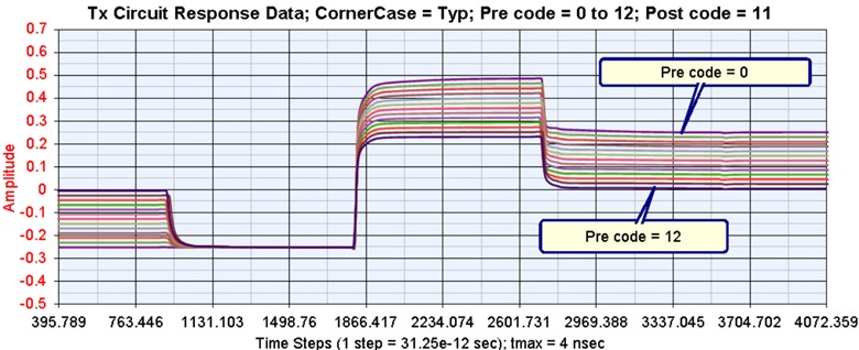
Figure 4. NXP Tx circuit waveforms collected
These response waveforms are at the Tx chip IBIS buffer output. The IBIS buffer characteristic is de-embedded from the response waveforms to obtain the AMI model characteristics. The AMI model converts the waveforms to a set of FFE tap gains, tap delays, and tap filtering for the specific bit rate and sample rate used in a simulation.
Thus, the combined Tx AMI model and Tx IBIS model provide the same characteristics as defined by the Tx circuit black box stimulus/response waveforms data.
The Silicon Creations Rx SerDes IP has this block diagram shown in Figure 5:

Figure 5. Silicon Creations Rx circuit design
This block diagram represents a receiver with CTLE, CDR, and DFE with three corner cases. The Rx input IBIS buffer included the chip on-die impedance and was defined using S-parameters for each corner case. A behavioral model for this Rx circuit was created with three corner cases: typical, slow, and fast.
The CTLE in this Rx circuit, inclusive of the Rx input IBIS buffer, was treated as a black box with stimulus/response waveforms captured from which the CTLE model can be extracted. The Rx input IBIS buffer included the chip on-die impedance and was defined using S-parameters for each corner case. The CTLE is LTI and has 32 states for each corner case. The IBIS-AMI modeling approach was based on collecting spice circuit simulation stimulus/response waveforms for all Rx CTLE states. The response waveforms were at the IBIS buffer input. The IBIS buffer characteristic had to be de-embedded from the response waveforms to obtain the Rx CTLE AMI model characteristics. Thus, the combined Rx IBIS buffer model and Rx CTLE AMI model provide the same characteristics as defined by the Rx IBIS/CTLE black box stimulus/response waveforms data.
The CDR in the Rx circuit was modeled using the OJTF corner frequency estimate for the Rx circuit CDR.
The DFE in the Rx circuit was modeled using 5 taps, with each tap defined with a set of states quantized with a set of tap codes.
As described in Figure 1, the total channel includes the Tx IBIS model, Tx Pkg, channel, Rx Pkg, and Rx IBIS model. For the current SerDes system, each of these total channel blocks were represented with S-parameter files. Support for Tx/Rx IBIS buffer with S-parameters was introduced with version 7.0 of the IBIS standard. The channel in the middle of the total channel had 25 dB loss at Nyquist (12.5 GHz).
Using NRZ data format, 25 Gbps, 32 samples per bit, and 100,000 analysis bits, the SerDes system was set up in the SerDes.com CS.
Simulations were run with these test cases: (2) total channel and Rx, and (3) Tx, total channel, and Rx. During each simulation, the Tx and/or Rx model initialization process selects the Tx and/or Rx states for optimal eye opening before the Rx DFE. These optimal settings are displayed in the SerDes.com message window.
Once the SerDes system channel simulation has been successfully set up, many simulations may be run to evaluate the Tx/Rx models over their various states. After many successful simulations, the SerDes system is verified to meet requirements.
Test case 2. With the Rx and total channel: the eye is about 36% open as shown in Figure 6.

Test case 3. With the Tx/Rx and total channel: the eye is about 56% open as shown in Figure 7.

The setup and use of a SerDes system example similar to the above is documented on the SerDesDesign.com website at Example_NRZ_IBIS_AMI_SerDes. The documented example does not use the NXP or SiliconCreations IBIS-AMI models but uses other IBIS-AMI models created from the SerDesDesign.com website.
The above test cases are only a sample of the full featured channel simulation capabilities available at SerDesDesign.com
Using Serdesdesign.com With Another Channel Characterization
Sometimes, the SerDes system described above is setup and simulated in another common channel simulator, such as the Keysight automatic debiting system (ADS) CS. However, an ADS license might not be available as needed to run simulation over many test conditions.
One of the key problems when setting up a SerDes system design in a different CS tool is that each CS tool does not give the same results. This fact has been observed by many and especially reported by Romi Mayder of Xilinx Inc. at the 2015 DesignCon conference for the top 6 EDA channel simulators in the industry. Each tool gives widely varying impulse modeling of S-parameters as well as widely varying channel BER performance [1]. Though this paper is dated, it still applies today. Additional observations have been posted on the web [2][3]. The key to getting the same simulation results among different CS tools is to use the same total channel impulse characterization.
Fortunately, the channel impulse response can be exported from a CS tool.
Such an impulse response, for example from the Keysight ADS Channel Simulator, can be imported into the SerDesDesign.com CS tools [4]. Thus, the SI engineer can explore the state space for their Tx/Rx IBIS-AMI models in a CS tool at no cost.
The results in the SerDesDesign.com CS tools will be (essentially) the same as would be obtained in the original CS tool. This similarity is because all AMI models are deterministic and perform the same in every CS tool. The primary difference in each CS tool is their characterization of the total channel. That difference is removed when the same total channel impulse response from one CS tool is used in another CS tool.
Ideally, the total channel impulse response derived from a CS tool has no high frequency aliasing (as the SerDesDesign.com tools). Unfortunately, sometimes the channel impulse response from another CS tool has a lot of high frequency aliasing. For test examples above, the impulse response exported from the Keysight ADS CS is shown in Figure 8 (time domain, left; frequency domain, right).
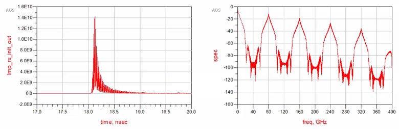
Since the simulation bit rate was 25 Gbps and 32 samples per bit was used, the simulation time step, tstep = 1/25e9/32 = 1.25e-12 sec. With this tstep, the sample rate = 1/tstep = 800 GHz. With this sample rate, the time domain signal will have frequency content up to (sample rate)/2 = 400 GHz. These plots are from the ADS data display where the ADS fs() function was used to derive the frequency domain response from the time domain impulse waveform.
Notice the high frequency aliasing in both plots. In the frequency domain plot, the high frequency aliasing is visible above the S-parameter upper frequency value of 40 GHz. A high level of high frequency aliasing may have a negative impact on the SerDes system analysis results.
For example, using Test Case 2 with this ADS impulse response and the Rx model in both the ADS and SerDesDesign.com CSs results in these eye density plots shown in Figure 9, with ADS on the left and SerDesDesign.com on the right.
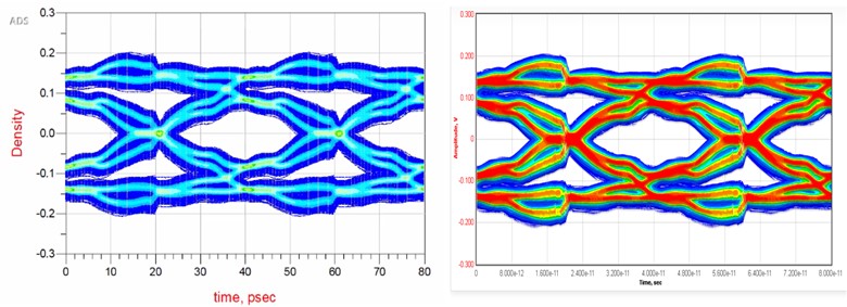 Figure 9. Eye density plot for SerDes system with ADS channel impulse and Rx model in ADS (left) and SerDesDesign.com (right)
Fortunately, SerDesDesign.com includes an anti-aliasing feature that can be used with an imported impulse response that has high frequency aliasing. In this case, the anti-aliasing filter can be enabled with corner frequency set to the S-parameters upper frequency; 40 GHz in this case. This filter does not produce any attenuation up to 40 GHz, but results in 3 dB attenuation at 60 GHz and 200 dB attenuation at 80 GHz. When applied, there will no longer be any high frequency aliasing and the resultant eye density plot will be the same as shown above in Figure 6.
Sometimes, even though the channel impulse response has a lot of high frequency aliasing, it becomes inconsequential when the combined Tx and Rx models provide enough filtering to suppress the high frequency aliasing.
This is true for Test Case 3 with the Tx model, this ADS impulse response, and the Rx model. In both the ADS and SerDesDesign.com CSs, the eye density plots will be essentially the same as shown in Figure 7.
Conclusion
SerDes CS, along with Tx/Rx IBIS-AMI models, are typically used by SI engineers to evaluate SerDes system margins. Oftentimes, the various commercial CS tools in the market cost many thousands of dollars for a yearly lease or to own. An SI engineer might not have access to their company CS tool due to unavailable licenses or the need to time-share access to their tool with others in the company.
Today, the SerDes channel simulation technology and the SerDes Tx/Rx modeling process has matured so that both are available for free using the cloud-based tools at SerDesDesign.com.
This paper reviewed tools available at SerDesDesign.com to provide the SI engineer a low cost (zero-cost) path for modeling and simulating SerDes systems. The free tools at SerDesDesign.com include behavioral modeling SerDes Tx/Rx designs in addition to use of Tx/Rx IBIS-AMI models per the IBIS standard. The SI engineer may even import the channel impulse characteristics from another CS tool and get the same results as their other tool. SerDesDesign.com also makes available features for a fee that includes converting Tx/Rx behavioral designs into IBIS-AMI models [5].
By using the zero-cost tools available at SerDesDesign.com, SI engineers have an easy-to-use alternative when their costly in-house CS tools are not available.
Acknowledgment
Acknowledgment is given to Jon Burnett and NXP for permission to reference the IBIS-AMI models created for them and use of their Keysight ADS CS copy. Acknowledgment is given to Blake Gray and Silicon Creations for permission to reference the IBIS-AMI models created for them and use of their Keysight ADS CS copy.
References
- Romi Mayder, R.M., et al. (2015, January). IBIS-AMI Model Simulations Over Six EDA Platforms. Xilinx.
- Baprawski, J. (2016). SerDes_Channel_Impulse_Modeling_with_Rambus. John Baprawski Inc.
- Baprawski, J. (2016). SerDes_Channel_Impulse_Modeling_with_SignalMetrics. John Baprawski Inc.
- Baprawski, J. (2021). Using an ADS Impulse Response. John Baprawski Inc.
- Baprawski, J. (2021). Summary of Features in SerDesDesign_Tools. John Baprawski Inc.
- Schnecker, M. (2009). Jitter Transfer Measurement in Clock Circuits. LeCroy Corperation. DesignCon 2009.